The short answer
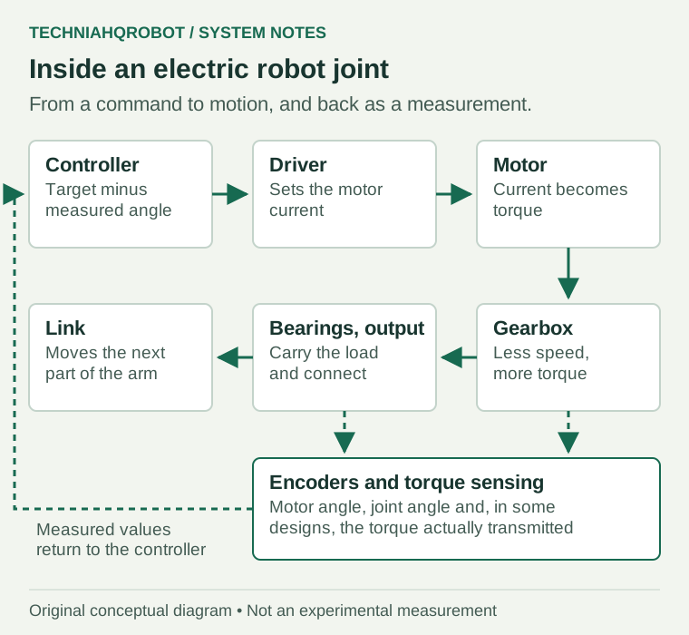
A robot joint is where two parts of a robot meet so that one can move relative to the other. In most electric robots, the joint contains a motor that creates motion, a gearbox that trades speed for force, bearings that carry the load, a sensor called an encoder that measures position, and a driver that controls the electric current to the motor. [1] [2]
Software compares where the joint should be with where the encoder says it is, then changes the motor current to reduce the difference. This happens many times per second. Robots differ in which parts they use and how they arrange them, so the description here is a common pattern, not a rule for every machine. [1] [3]
A simple picture: your elbow
Bend your elbow. Two bones, the upper arm and the forearm, are connected at a joint. Muscles pull on the bones to move them. Even with your eyes closed, you know roughly how bent your elbow is, because sensors in your muscles and joints tell your brain.
A robot arm copies this layout. The rigid parts are called links. The joint connects two links. An actuator, usually an electric motor with a gearbox, plays the role of the muscle. An encoder plays the role of your sense of position. A controller plays the role of the part of your nervous system that keeps correcting the movement.
The comparison stops there. Your muscles can only pull, while an electric motor can drive a joint in both directions. Your joints are padded, slightly flexible and repair themselves. A robot joint wears out, and it reports its angle as a number with a fixed resolution.
Joint types and degrees of freedom
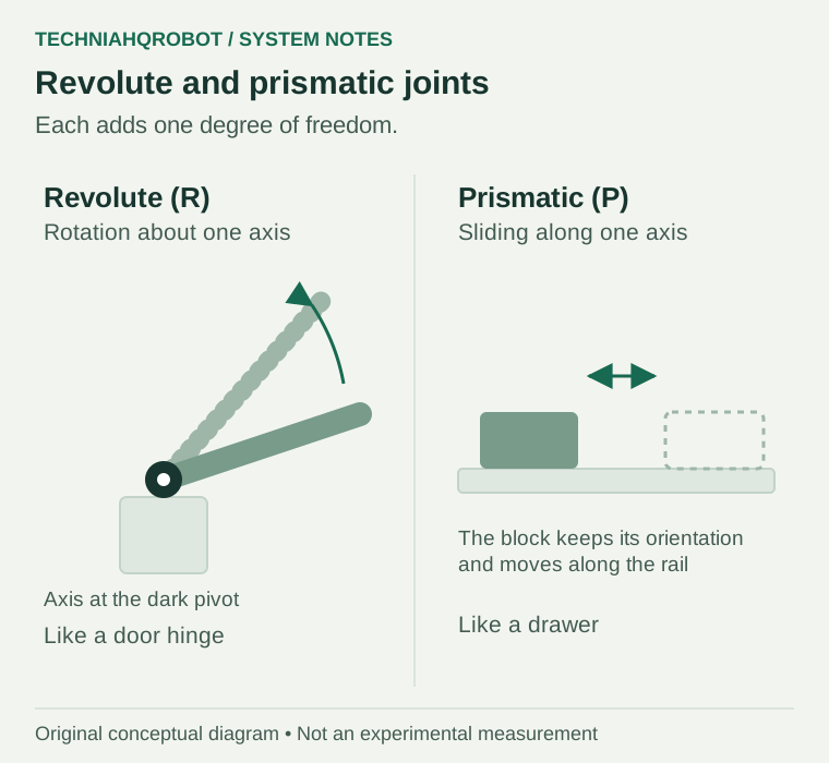
A degree of freedom, or DOF, is one independent way something can move. The two joints that appear most often in robots each give one degree of freedom. A revolute joint, also called a hinge joint, rotates about an axis, like a door hinge. A prismatic joint slides along an axis, like a drawer. [2]
| Joint | Motion | Degrees of freedom | Everyday comparison |
|---|---|---|---|
| Revolute (R) | Rotation about one axis | 1 | Door hinge |
| Prismatic (P) | Sliding along one axis | 1 | Drawer |
| Screw or helical (H) | Rotation coupled to sliding | 1 | Nut on a bolt |
| Cylindrical (C) | Independent rotation and sliding on one axis | 2 | Telescopic shaft that can also turn |
| Universal (U) | Rotation about two crossing axes | 2 | Drive-shaft joint |
| Spherical (S) | Rotation about three axes | 3 | Ball-and-socket joint |
Motorized robots usually build multi-DOF motion from several one-DOF joints in a chain, because one motor drives one axis. A six-axis industrial arm such as the Universal Robots UR5e has six rotating joints, each listed with a ±360° range, and an 850 mm reach. Unitree’s G1 example code names three shoulder joints per arm, shoulder pitch, roll and yaw, followed by an elbow and three wrist joints. Three revolute joints in a row approximate what a human shoulder does with one ball-and-socket joint. [4] [3]
What is inside an electric joint
| Part | What it does | What can limit it |
|---|---|---|
| Motor | Turns electric current into torque. In a brushed or brushless DC motor, torque is roughly proportional to current. | Winding temperature, maximum current, magnet strength |
| Gearbox (reducer) | Lowers speed and raises torque by its reduction ratio | Friction, backlash, flexibility, wear |
| Bearings | Carry loads in directions other than the joint rotation and keep the shaft aligned | Load rating, wear, contamination |
| Output shaft or flange | Connects the joint to the next link | Stiffness and fastening |
| Encoder | Measures angle, either at the motor or at the joint output | Resolution, mounting, noise |
| Driver | Power electronics that regulate the current sent to the motor | Current limit, heat, communication delay |
| Torque sensor (some designs) | Measures the torque actually transmitted | Cost, stiffness, calibration |
Some joints combine all of these in one module. Kinova lists smart actuators with integrated torque sensors that also report position, current, voltage and temperature for its Gen3 arm. Other robots keep the motor, gearbox and sensors as separate parts. [7]
Why joints use gears
Electric motors are good at spinning fast with little torque. Robot joints usually need the opposite: slow movement with a lot of torque. A gearbox with a reduction ratio N divides the speed by N and multiplies the torque by about N, minus friction losses. Mechanical power, torque times angular speed, cannot increase through a gearbox; it can only be traded and partly lost as heat. [1]
Gearing has a cost. The rotor inertia felt at the joint output, called reflected inertia, grows with the square of the gear ratio. Wensing and colleagues give the MIT Cheetah leg actuator, with a single-stage planetary gear of 5.8:1, a reflected inertia of 0.0102 kg·m², and compare it with a HUBO joint using a 160:1 reduction at 0.0852 kg·m². A low ratio makes a joint easier to push from the outside and better at absorbing impacts. A high ratio gives more torque from a small motor but makes the joint stiff and hard to backdrive. [8]
| Gear type | How it works | Documented example or claim |
|---|---|---|
| Planetary | A central sun gear drives several planet gears that roll inside a ring gear | MIT Cheetah: one-stage planetary, 5.8:1, chosen for low reflected inertia |
| Strain wave (harmonic) | An elliptical wave generator flexes a thin toothed cup inside a rigid ring with two more teeth, so each input turn shifts the cup by two teeth | Harmonic Drive claims zero backlash and high ratios in a single stage |
| Multi-stage spur gears | Several gear pairs in series multiply the reduction | The ROBOTIS XM430-W350 servo lists a 353.5:1 ratio |
| Direct or quasi-direct drive | No gearbox, or a very low ratio, with a large motor | Easier to backdrive; needs a motor with high torque for its size |
No single transmission is best. The documented examples in the table use three different ones, each chosen for a different job: impact-tolerant legs, compact high-ratio joints and a small low-cost servo. A robot’s own documentation, not its category, tells you which one it uses. [9] [8] [10]
How a joint measures its position
An encoder converts rotation into a number. An incremental encoder counts small steps from a starting point, so the robot has to find a reference after it powers on. An absolute encoder reports a unique value for each position, so the angle is known immediately. The ROBOTIS XM430-W350 manual lists a contactless 12-bit absolute encoder with 4,096 counts per revolution, which is 360° ÷ 4,096 ≈ 0.088° per count. [1] [10]
Where the encoder sits matters. An encoder on the motor shaft turns N times for each output turn, so it gives fine resolution, but it cannot see backlash or flexing in the gearbox. An encoder on the joint output measures the link directly, including those effects. Some joints carry both and compare them. [1]
Resolution at the joint becomes distance at the hand. In the worked example below, a hand 0.65 m from the base moves about 1 mm when the base joint turns by 0.088°. Small angle errors near the base of an arm matter more than the same errors near the wrist.
Commanded position is not measured position
The controller sends a target; the encoder reports what happened. The difference is the tracking error. It grows when the joint is loaded, when gravity pulls the arm, when the target moves fast, when the gearbox flexes or has play, and when the feedback gains are set low on purpose to keep the joint soft. [1] [11]
Unitree’s G1 example shows a common command format. Each motor receives a target angle q, a target velocity dq, a stiffness gain kp, a damping gain kd and a feedforward torque tau, and the example runs its loop every 2 ms. The motor controller turns these into torque roughly as tau + kp × (q − measured angle) + kd × (dq − measured velocity). Setting kp high makes the joint follow the target tightly; setting it low makes the joint yield when something pushes it. [3] [12]
This also answers a common question: what is the difference between a servo motor and a robot actuator? A servo, in the hobby and small-robot sense, is a packaged motor, gearbox, encoder and controller that tracks a commanded position. The XM430-W350 is one, and its manual lists current, velocity, position, extended position, current-based position and PWM modes. “Robot actuator” is the broader term for anything that makes a robot move: a smart servo, a custom joint module with torque sensing, a hydraulic cylinder or a pneumatic muscle. [10]
How joints control force as well as position
A joint can push as well as move. Because motor torque is roughly proportional to current, measuring current gives an estimate of joint torque without a separate sensor. The MIT Cheetah used closed-loop motor current control to produce desired torques and estimated foot force from the measured winding current. Its authors note that friction and the flexibility of the leg limit how accurate and fast that estimate is. [8] [5]
Other robots measure force directly. Kinova places torque sensors in each Gen3 actuator, and Universal Robots lists a built-in force/torque sensor on the UR5e with an accuracy of 4 N. Direct sensing helps when friction in a high-ratio gearbox hides the external force from the motor current. [7] [4]
Impedance control combines position and force. Instead of holding a position rigidly, the controller makes the joint behave like a virtual spring and damper around the target: the further it is pushed away, the harder it pushes back. This is useful when a robot touches people or uncertain objects. [13]
Backlash, friction, flexibility, heat and wear
| Effect | What it is | What it causes |
|---|---|---|
| Backlash | Free play between gear teeth when the direction of motion reverses | A small dead zone in which the motor turns but the link does not |
| Friction | Resistance in gears, bearings and seals | Lost torque, heat, and a joint that resists small corrections |
| Compliance | Elastic flexing of gears, shafts and links under load | The link lags behind the motor and can vibrate |
| Heat | Current through the motor windings produces heat that must escape | Continuous torque is lower than peak torque; drivers reduce current or shut down when hot |
| Wear | Gradual loss of material and lubrication in moving parts | Growing backlash and noise over many cycles |
Heat deserves special attention, because a joint can produce a peak torque for a short time but not continuously. The ROBOTIS manual describes temperature monitoring and shutdown, and maxon explains that continuous motor output depends on winding temperature and how well heat is removed. [10] [6]
The thermal limit of a legged robot’s joints is worked through in continuous torque and heat still limit a leg.
Joint limits and collision protection
Joints have several kinds of limit. Software limits stop a target from leaving the allowed range. Mechanical hard stops catch the joint if software fails. Current limits cap the torque a driver will supply. Collision detection compares the torque or current that the controller expected with what it measures; a large unexpected difference suggests the arm has hit something, and the controller stops or yields. [10] [11]
Certified safety functions are a separate layer from ordinary control. Universal Robots lists 23 configurable safety functions on the UR5e, rated PL d Category 3 under EN ISO 13849-1. A rating like this describes the safety function, not whether a particular application around the robot is safe. [4]
How that application-level judgement works is explained in humanoid robot safety standards and certification.
From joint angles to the hand
Once the joints are clear, the next question is where they put the robot’s hand, also called the end effector. Forward kinematics calculates the hand’s position and orientation from the joint angles and link lengths. Inverse kinematics does the reverse: it finds joint angles that put the hand at a desired pose. [14] [2]
Take a flat two-link arm with a 0.4 m upper link and a 0.3 m forearm. With the shoulder at angle θ1 and the elbow at θ2, the hand sits at x = 0.4 cos θ1 + 0.3 cos(θ1 + θ2) and y = 0.4 sin θ1 + 0.3 sin(θ1 + θ2), and points at angle θ1 + θ2. [14]
| Joint angles | Hand position (x, y) | Change |
|---|---|---|
| θ1 = 30°, θ2 = 45° | 0.424 m, 0.490 m | Starting pose, 0.648 m from the shoulder |
| θ1 = 31°, θ2 = 45° | 0.415 m, 0.497 m | 1° at the shoulder moves the hand about 11 mm |
| θ1 = 30°, θ2 = 46° | 0.419 m, 0.492 m | 1° at the elbow moves the hand about 5 mm |
Changing one joint angle swings everything beyond it. The shoulder moves both links, so it moves the hand further than the elbow does for the same angle. Both changes also rotate the hand by 1°. Inverse kinematics usually has more than one answer, such as elbow up or elbow down, and sometimes none, when the target is out of reach. [14]
Inverse kinematics on a walking robot is used in how humanoid robots walk without falling, where a foot target becomes hip, knee and ankle angles.
Three joints in practice
A six-axis industrial arm
The UR5e has six rotating joints, each listed at ±360° and up to 180°/s, a 5 kg payload and ±0.03 mm pose repeatability. Repeatability measures how closely the arm returns to a taught pose, not how accurately it reaches a pose calculated from a model. [4]
A humanoid shoulder
In the G1 example code, each arm runs shoulder pitch, roll and yaw, then the elbow, then wrist roll, pitch and yaw: seven joints from shoulder to hand. Three intersecting or near-intersecting axes at the shoulder let the arm point in many directions, but they also create configurations where two axes line up and one direction of motion is lost, which is called a singularity. [3] [15]
A robot gripper
A gripper is a joint whose job is to squeeze. Robotiq lists an adjustable stroke of 85 mm, an adjustable grip force from 20 to 235 N and an adjustable closing speed of 20 to 150 mm/s for its 2F-85. Adjustable force is the point: a metal part and a paper cup need very different squeezes. [16]
Choosing a gripper and setting its force is covered in how collaborative robots and grippers work.
How engineers test a joint, and where it fails
| Test | What it checks | Typical failure it reveals |
|---|---|---|
| Step and tracking tests | How fast and how closely the joint follows a target | Lag, overshoot or oscillation from gains, compliance or delay |
| Direction-reversal test | Motion of the link when the motor reverses | Backlash dead zone |
| Thermal run | Torque held over minutes while temperature is logged | Overheating, current derating or shutdown |
| Backdrive test | Torque needed to move the joint from outside with power off | High friction or reflected inertia |
| Collision test | Response when the link meets an obstacle | Late or missing stop, excessive contact force |
| Life test | Many repeated cycles under load | Wear, growing play, lubrication loss |
Each test describes one joint under stated conditions. A peak torque in a datasheet, a smooth motion in a video and a long life test answer different questions, and none of them alone shows how the joint behaves inside a full robot doing real work.
Sources and verification
- Actuation, gearing and friction ↗Kevin Lynch and Frank Park, Northwestern University · Read 8 October 2026
Author-provided textbook supplement covering electric motors, encoder measurements, gear ratios, losses and reflected rotor inertia.
- Modern Robotics, Chapter 2: configuration space and joint types ↗Kevin M. Lynch and Frank C. Park, Northwestern University · Read 15 October 2026
Authors' preprint dated 29 November 2016 of the Cambridge University Press textbook. Table 2.1 lists revolute, prismatic and screw joints with one degree of freedom, cylindrical and universal with two, and spherical with three. Used for joint definitions only.
- Unitree G1 low-level example joint index ↗Unitree Robotics · Read 15 October 2026
Source file read for the 29-motor joint index, including LeftShoulderPitch, LeftShoulderRoll, LeftShoulderYaw, LeftElbow and three wrist joints per arm, the q, dq, kp, kd and tau command fields and a 2 ms control period in the example.
- UR5e technical specifications ↗Universal Robots · Read 15 October 2026
Manual page read for 5 kg payload, 850 mm reach, six rotating joints with ±360° range, 180°/s maximum joint speed, ±0.03 mm pose repeatability per ISO 9283, 4 N force/torque sensor accuracy, 20.7 kg arm mass and 23 configurable safety functions rated PL d Category 3 under EN ISO 13849-1.
- DC and EC motor equations and thermal behaviour ↗maxon · Read 8 October 2026
November 2014 motor reference. Printed pages 42 and 46 explain power, winding losses and thermal behaviour. These are motor principles, not G1 measurements.
- Continuous operation range of BLDC motors ↗maxon · Read 8 October 2026
Updated 29 August 2024. Continuous output depends on winding temperature and heat dissipation; example temperature limits belong to the documented motor.
- Kinova Gen3 ultra lightweight robot one-pager (2026) ↗Kinova · Read 15 October 2026
Manufacturer sheet read for 6-DoF and 7-DoF versions, 2.0 kg full-range and 4.0 kg mid-range continuous payload excluding the gripper, 891 mm and 902 mm reach, 7.2 kg and 8.2 kg mass, smart actuators with integrated torque sensors, an optional vision module, Kortex software with ROS Noetic and ROS 2 Humble support, 36 W average power and 50 cm/s maximum Cartesian speed. No repeatability figure is given.
- Proprioceptive Actuator Design in the MIT Cheetah ↗Patrick M. Wensing and colleagues, IEEE Transactions on Robotics · Read 12 October 2026
2017 TRO paper. Proprioceptive, low-impedance actuation. Bounding contacts down to 85 ms and peak forces over 450 N. Continuous torque and thermal capacity are named as design metrics. No Optimus data.
- Harmonic Drive strain wave gearing technology ↗Harmonic Drive LLC · Read 15 October 2026
Manufacturer description of the wave generator, flexspline and circular spline, the two-tooth difference and the manufacturer's zero-backlash and compactness claims. Treated as manufacturer claims, not independent tests.
- DYNAMIXEL XM430-W350 actuator manual ↗ROBOTIS · Read 8 October 2026
Manufacturer manual covering mode-dependent current limits, temperature monitoring and shutdown. Used as a specific actuator example, not as a description of T800 hardware.
- Robotic Manipulation chapter on robot hardware ↗Russ Tedrake, MIT · Read 8 October 2026
Position and torque control, transmissions, parallel grippers and underactuated fingers.
- Unitree G1 low-level Python example ↗Unitree Robotics · Read 8 October 2026
Manufacturer source code for a 29-motor G1 configuration. The command contains position, velocity, stiffness, damping and feedforward torque fields. It does not disclose a complete walking or fighting policy.
- Variable impedance control and learning: a review ↗Fares J. Abu-Dakka and Matteo Saveriano · Read 15 October 2026
Read for the definition of impedance control as a virtual spring-damper relationship between motion and force, and its duality with admittance control.
- Numerical inverse kinematics ↗Kevin Lynch and Frank Park, Northwestern University · Read 8 October 2026
Author-provided textbook supplement covering forward and inverse kinematics. Joint geometry alone does not establish dynamic feasibility.
- MoveIt Realtime Servo ↗MoveIt project · Read 8 October 2026
Official documentation describes joint and hand commands, joint limits, singularity checks and optional collision checking. Motion smoothing is also optional.
- Robotiq 2F-85 and 2F-140 adaptive gripper product sheet ↗Robotiq · Read 15 October 2026
Product sheet read for the 2F-85: 85 mm adjustable stroke, 20 to 235 N adjustable grip force, 5 kg form-fit and friction payloads, 20 to 150 mm/s closing speed, 0.9 kg mass and 0.4 mm fingertip position resolution. The sheet points to support.robotiq.com for official figures.
Article history
First version, written after a site audit found joint mechanics, gearing and encoders only as fragments inside humanoid and actuator articles.
Report a correction