The short answer
A powered exoskeleton is a wearable robot that adds force to a person’s joints. Sensors measure how the wearer is moving, software works out what phase of a movement they are in and how much help to give, and motors deliver that help through a frame or through straps and cables. The person stays inside the control loop the whole time. [1]
There is no single way to do this. Exoskeletons for paralyzed users, soft suits for people recovering from a stroke, and passive back supports for warehouse workers use different hardware, different controllers and different safety rules. The review by Baud and colleagues describes “a considerable number of different controllers” in the research literature. [1]
A simple picture: helping someone push a heavy door
Imagine helping a friend push open a heavy door. You need to push when they push, in the same direction, and roughly as hard as they need. Push too early and they stumble forward. Push too late and you add nothing. Push in the wrong direction and you fight them.
An exoskeleton faces the same problem, many times per step. The comparison has a limit: you can see your friend’s face and hear them, but the device cannot read the wearer’s mind. It only has its sensors, so it estimates what the wearer is trying to do from joint angles, foot pressure, body motion and sometimes muscle signals, and it can be wrong.
Rigid exoskeletons and soft exosuits
| Rigid exoskeleton | Soft exosuit | |
|---|---|---|
| Structure | Rigid links and powered joints running alongside the limbs | Textiles anchored to the body, with cables that pull across joints |
| Where the load goes | The frame can carry its own weight and transfer load to the ground | Forces pass through the wearer’s own bones and joints |
| Typical use | Standing and walking for people with paralyzed or weakened limbs | Partial assistance for people who can already walk |
| Main difficulty | Mass and keeping robot joints aligned with human joints | Delivering enough force without the textile slipping |
| Documented example | US rules classify powered lower-extremity exoskeletons as prescription, Class II medical devices | Awad and colleagues tested a 0.9 kg exosuit that pulls the ankle with Bowden cables |
The Harvard exosuit in the 2017 stroke study was worn on the weaker leg, anchored by textile bands at the waist and calf. One cable in front of the ankle lifted the foot during swing, which helps the toes clear the ground. One behind it helped the ankle push off during stance. On the treadmill the actuator sat off the body; for walking overground, a 2.63 kg actuator and a 0.56 kg battery rode on a waist belt. [3]
Rehabilitation, mobility and industrial devices
Medical exoskeletons are regulated as medical devices. In the United States, the rule for powered lower-extremity exoskeletons requires clinical testing that records adverse events, software verification and hazard analysis, electrical, battery and electromagnetic testing, a training program for clinicians, users and companions, and labeling that warns against risky activities and environments. [2]
Industrial exoskeletons support workers rather than treat a condition. NIOSH distinguishes passive devices, which use springs and counterweights, from active ones powered by motors, pneumatics or hydraulics, and lists back, shoulder and arm, tool-holding and leg-assist types. It also notes that most studies so far have involved small numbers of participants, mostly in laboratories. [4]
The international personal care robot standard ISO 13482 covers physical assistant robots, but its scope excludes robots used as medical devices. A rehabilitation exoskeleton and a factory support suit can look similar and still fall under different rules. [5]
How the parts interact
A wearable robot is a loop with a person in it. The wearer moves. Sensors measure the movement. Software estimates the situation and decides on an assistance command. A low-level controller drives the motor to produce that command. The force travels through a gearbox, a frame or cables, and cuffs or straps into the wearer’s body, which changes the next movement. [1]
Baud and colleagues organize controllers in three levels. The high level selects the overall mode, such as standing, walking or climbing, and mode changes are usually separated by at least several seconds. The mid level runs every control cycle: it detects the gait phase and computes the desired joint torque or position. The low level makes the actuator produce that output, using position or torque controllers. The authors note that most research effort goes into the mid level. [1]
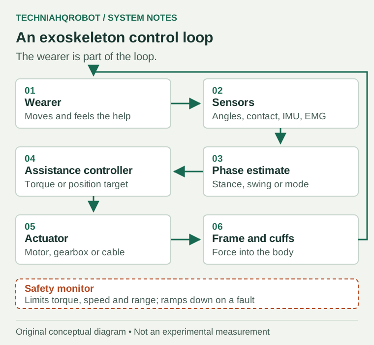
What the sensors measure
| Sensor | What it measures | Strengths and limits |
|---|---|---|
| Joint encoder | The angle of the exoskeleton joint | Precise and fast, but it measures the device, not the human joint, which can move differently |
| Motor current | An estimate of motor torque | No extra sensor needed; friction and flexibility make the estimate less accurate |
| Force or load cell | Force in a cable, strap or link | Measures what is actually delivered; adds cost and wiring |
| Foot switch or pressure insole | When and where the foot touches the ground | A heel switch is the most common gait-event trigger in the reviewed controllers |
| IMU | Rotation and acceleration of a body segment | Detects gait events and body motion; drifts if integrated for long |
| Surface EMG | Electrical activity of muscles through the skin | Can signal intent 50 to 100 ms before motion; sensitive to electrode shift, fatigue and noise |
The 2017 exosuit combined several of these: gyroscopes on each shoe split each step into sub-phases in real time, load cells in the textile measured the delivered force, and potentiometers measured cable position. [3]
Estimating what the wearer is trying to do
Intention cannot be measured directly. Controllers infer it from patterns: a heel strike marks the start of stance, a rising shank angular velocity suggests the leg is swinging forward, a lean of the trunk may signal the start of a step. For people with paraplegia, Baud and colleagues note that IMU data often comes from the upper body, because the legs themselves cannot start the movement. [1]
Muscle signals are attractive because they appear before the movement does. Fu and colleagues report that EMG onset can be detected about 50 to 100 ms before physical motion. The same chapter lists the problems that make EMG hard to use day to day: signals from neighboring muscles mixing together, drift and motion artifacts, electrodes shifting during or between sessions, muscle fatigue changing the signal, and models trained on short recordings that do not stay reliable. [6]
A wrong estimate is not a small error. If the controller thinks the wearer is in stance while the foot is actually swinging, it applies the wrong torque at the wrong moment. Good designs limit how much harm one wrong estimate can do.
Position, torque and impedance control
| Control mode | What the controller tries to do | When it fits | Main risk |
|---|---|---|---|
| Position control | Make the joint follow a planned trajectory | The wearer cannot move the limb alone | The device fights a wearer who moves differently |
| Torque control | Add a chosen torque, often as a function of gait phase | The wearer moves and needs partial help | Mistimed torque pushes at the wrong moment |
| Impedance control | Behave like a virtual spring and damper around a target | Assistance should yield when the wearer deviates | Too stiff feels like position control; too soft gives little help |
| Transparent (zero-torque) mode | Cancel the device’s own friction and inertia as far as possible | Letting the wearer move freely, or measuring natural gait | Imperfect cancellation leaves drag |
The low-level loop and the gait-phase estimate may run on different processors, and every link between them, wired or wireless, adds delay. Timing matters because assistance is tied to a phase of a step that lasts a fraction of a second. In the exosuit study, the authors tested two timings for the start of push-off assistance and found that the best one varied between individuals. [3] [1]
The joint-level ideas behind these modes are explained in how robot joints and actuators work.
Worked example: a powered knee during stance
When the heel lands, the knee bends slightly as it takes the body’s weight, then straightens again as the body passes over the foot. A person with weak thigh muscles may find that early stance hard. A powered knee can add an extension torque during that part of the step and stay out of the way during swing.
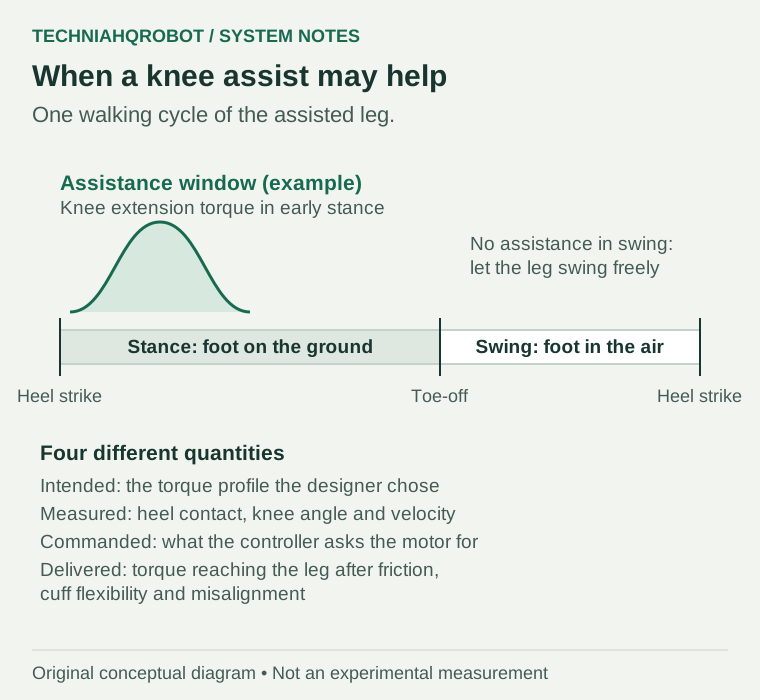
| Quantity | In this example | How it is known |
|---|---|---|
| Intended assistance | An extension torque in early stance, rising and falling smoothly, zero in swing | Chosen by the designer and adjusted for the wearer |
| Measured motion | Heel contact, knee angle and knee angular velocity | Heel switch or insole, joint encoder, IMU |
| Controller response | When contact is detected and the knee starts to bend, the commanded torque follows the planned profile, scaled down if the knee moves unexpectedly | Software running each control cycle |
| Delivered force | The torque that reaches the leg through the gearbox, frame and cuffs | Torque or load sensor, or an estimate from motor current |
These four numbers are different, and the gaps between them are where problems hide. Gear friction, flexible cuffs and a knee axis that does not line up with the device all make delivered torque differ from commanded torque. A report that shows only the intended profile says nothing about what the wearer actually received. [9] [7]
Keeping the robot joint aligned with the human joint
A human knee is not a perfect hinge. Its rotation axis shifts as it bends, and soft tissue lets the cuffs move against the bone. Torricelli and colleagues found the largest mismatch between human and exoskeleton motion at the knee during gait, and point out that the human and exoskeleton knee axes differ. They list energy loss, less accurate control of the limb, and discomfort and pain from skin abrasion as consequences. [9]
Designers respond with adjustable link lengths, careful fitting and, in some devices, extra unpowered joints that let the frame follow the body. The test that matters is measuring interaction forces at the cuffs while the wearer walks, not only checking that the device’s own joints moved as commanded.
Safety: limits, stops and failure behaviour
| Hazard | Example | Typical protection |
|---|---|---|
| Excess torque or speed | A controller error drives the knee hard | Torque, speed and current limits in the driver |
| Motion beyond the body’s range | A powered joint moves past what the human joint allows | Mechanical and software range-of-motion stops |
| Sensor failure | An encoder or foot switch gives a bad value | Plausibility checks; ramp torque down to zero |
| Loss of balance | The device shifts the wearer’s centre of gravity | Supervision, training and a defined fall response |
| Battery fault | Overheating pack | Battery protection and testing |
| Skin and nerve injury | Prolonged cuff pressure | Fitting, padding and limited wear time |
NIOSH lists muscle strain if a powered device moves beyond a joint’s normal range, burns from battery problems, pressure wounds and compressed nerves, and balance problems from a shifted centre of gravity among the potential risks of industrial exoskeletons. The US rule for medical exoskeletons requires verification of manual override controls where present and training in the use of safety features. [4] [2]
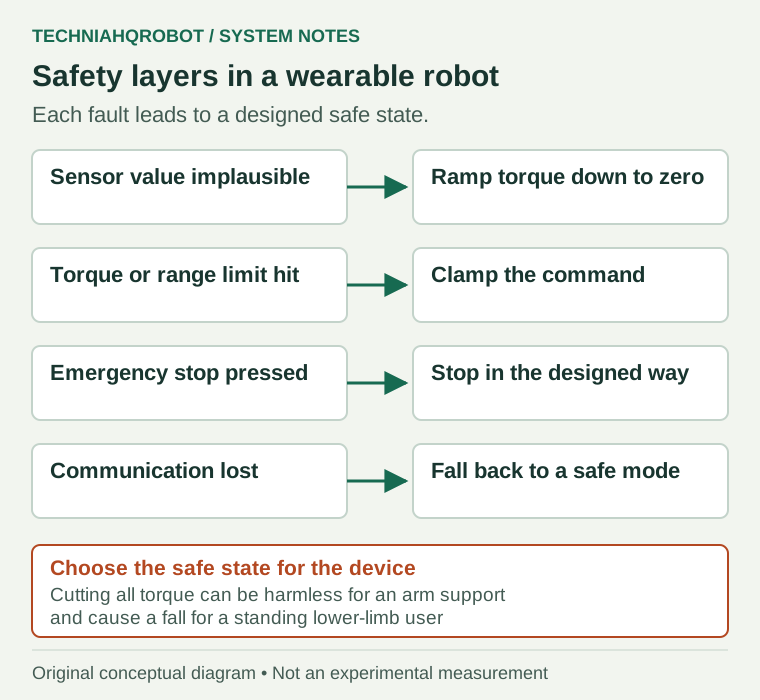
The safe state needs thought. Cutting all power to a shoulder-support suit is usually harmless. Cutting all power to a lower-limb exoskeleton that is holding a person upright can cause a fall. A stop in a wearable robot is a designed behaviour, not just an off switch.
How to read an exoskeleton result
The 2017 exosuit study is a good model of a careful claim. In nine people in the chronic phase of stroke recovery, powered assistance on the treadmill raised peak ankle dorsiflexion in swing by about 5.3° and reduced the energy cost of walking by 10%, compared with wearing the suit unpowered. Push-off on the weaker side rose by 11% in the seven participants whose push-off could be measured separately for each leg. The authors state that the study measured immediate effects only, not long-term therapy. [3]
- Who wore the device, and how many people took part?
- Was the comparison made against no device, an unpowered device or a different controller?
- Was walking measured on a treadmill, overground or in daily life?
- Does the report show delivered torque, or only the commanded profile?
- How were sensor failures, falls and stops handled during testing?
- Is the result an immediate effect or a change that lasted?
Sources and verification
- Review of control strategies for lower-limb exoskeletons to assist gait ↗Romain Baud and colleagues, Journal of NeuroEngineering and Rehabilitation 18, 119 (2021) · Read 15 October 2026
Read for the high-, mid- and low-level control hierarchy, mode changes separated by at least several seconds, heel foot switches as the most common gait-event trigger, IMU and joint sensing for movement recognition, low-level position or torque controllers, and the authors' statement that many different controllers exist and are not directly compared.
- 21 CFR 890.3480, Powered lower extremity exoskeleton ↗US Code of Federal Regulations, via Cornell Legal Information Institute · Read 15 October 2026
Read for the identification as a prescription, externally worn powered orthosis for paralyzed or weakened limbs, Class II special controls including clinical testing with adverse events, software verification and hazard analysis, electrical, battery and EMC testing, training, labeling and verification of manual override controls where present. US rule only.
- A soft robotic exosuit improves walking in patients after stroke ↗Louis N. Awad and colleagues, Science Translational Medicine 9(400), eaai9084 (26 July 2017) · Read 15 October 2026
Author-hosted PDF read for the unilateral textile exosuit at the waist and calf, Bowden cables for plantarflexion in stance and dorsiflexion in swing, shoe-mounted gyroscopes for gait events, load cells and potentiometers, a 0.9 kg suit, an off-board actuator on the treadmill and a 2.63 kg body-worn actuator overground, nine chronic stroke participants and immediate-effect results.
- Industrial Exoskeletons ↗NIOSH Science Blog, US Centers for Disease Control and Prevention · Read 15 October 2026
Page last updated 25 November 2024. Read for passive and active industrial exoskeletons, back, shoulder and arm, tool-support and leg types, the listed potential risks, and NIOSH's statements that most studies are small and laboratory based.
- ISO 13482:2014 scope and revision status ↗ISO · Read 8 October 2026
Published and marked for revision at the check date.
- Challenges and Trends of Machine Learning in the Myoelectric Control System for Upper Limb Exoskeletons and Exosuits ↗Jirui Fu and colleagues, IntechOpen (2023) · Read 15 October 2026
Book chapter read for surface EMG limitations: crosstalk, drift and motion artifacts, electrode shift within and between sessions, muscle fatigue, changing signal characteristics and the need for robust training data, and the 50 to 100 ms by which EMG onset can precede motion.
- Proprioceptive Actuator Design in the MIT Cheetah ↗Patrick M. Wensing and colleagues, IEEE Transactions on Robotics · Read 12 October 2026
2017 TRO paper. Proprioceptive, low-impedance actuation. Bounding contacts down to 85 ms and peak forces over 450 N. Continuous torque and thermal capacity are named as design metrics. No Optimus data.
- Variable impedance control and learning: a review ↗Fares J. Abu-Dakka and Matteo Saveriano · Read 15 October 2026
Read for the definition of impedance control as a virtual spring-damper relationship between motion and force, and its duality with admittance control.
- A Subject-Specific Kinematic Model to Predict Human Motion in Exoskeleton-Assisted Gait ↗Diego Torricelli and colleagues, Frontiers in Neurorobotics 12:18 (2018) · Read 15 October 2026
Read for relative motion between the human and exoskeleton, the knee showing the largest misalignment during gait, differing knee rotation axes, soft-tissue compliance, and consequences including energy loss, inaccurate control and skin abrasion.
Article history
First version, written after a site audit found no page on exoskeleton or exosuit control.
Report a correction